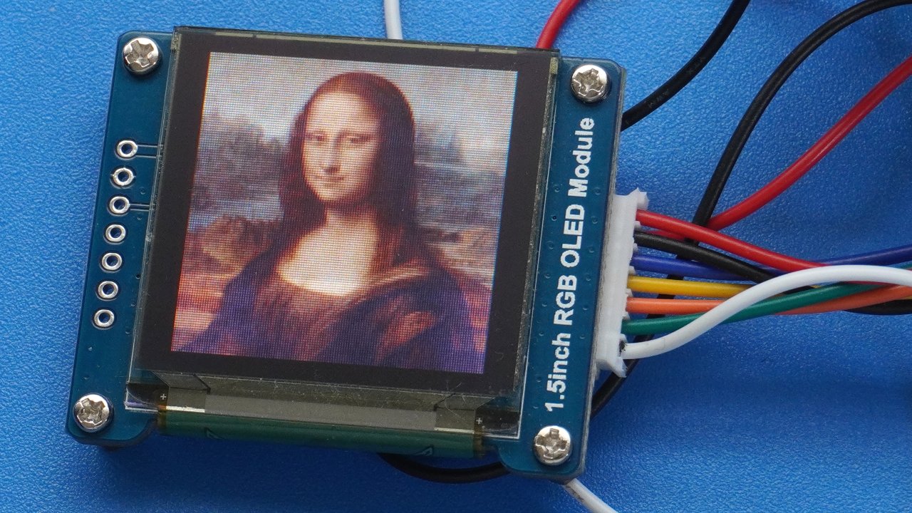
Here’s how to display full colour images on an OLED display using an ESP32 microcontroller. I’m using the amazing Waveshare 1.5 inch OLED, which offers 16 bit colour in a resolution of 128×128 pixels. Although Waveshare have their own graphics library, this tutorial uses the popular Adafruit GFX Library. The display is compatible with the SSD1351 library.
The images are stored in RAM, and not on an external SD card or downloaded over Wifi. There’s a really useful utility called LCD Image Converter that I find really useful for converting images into code for use in embedded devices like the Arduino Uno, ESP32 or ESP8266.
The code here could potentially be used on an Arduino Uno, but images like these really gobble up memory, and the Arduino just doesn’t have enough of it. So for graphics heavy Internet of Things devices the ESP32, ESP32 CAM or ESP8266 are better choices.
I believe the ESP32 memory can hold a maximum of 16 128×128 16-bit images. However this wouldn’t need much space for application code. If you need to store more then it would be better to store the images on an SD card, then load them in as required.
Source Code (Displays Single Image)
Important: I haven’t included the data for the image because browsers get very suspicious of a whole load of hexadecimal codes. To use this code yourself you need to make a 128 x 128 pixel image and save out the hex data from LCD Image Converter like I demonstrate in the video. Copy and paste the data in so it replaces DATA_GOES_HERE in the array called imageData.
//Displays a 16 bit image on the Waveshare 1.5 inch RGB OLED module
//using the Adafruit GFX library


// Screen dimensions
#define SCREEN_WIDTH  128
#define SCREEN_HEIGHT 128

#include <Adafruit_GFX.h>
#include <Adafruit_SSD1351.h>
#include <SPI.h>

//Many thanks to redditors wi1k1n and roaringmuffin for figuring out the ESP32 pins
//These work whereas the suggested pins in Examples/Adafruit SSD1351 library/test
//do not work with the Waveshare 1.5 inch RGB OLED module

//These connections must stay like this due to use of hardware SPI
#define SCLK_PIN GPIO_NUM_18 // CLK (or use constant SCK)
#define MOSI_PIN GPIO_NUM_23 // DIN (or use constant MOSI)

//These connections can be changed to other pins if desired
#define DC_PIN   GPIO_NUM_2
#define CS_PIN   GPIO_NUM_0
#define RST_PIN  GPIO_NUM_4

// Color definitions
#define	BLACK           0x0000
#define	BLUE            0x001F
#define	RED             0xF800
#define	GREEN           0x07E0
#define CYAN            0x07FF
#define MAGENTA         0xF81F
#define YELLOW          0xFFE0
#define WHITE           0xFFFF

Adafruit_SSD1351 tft = Adafruit_SSD1351(SCREEN_WIDTH, SCREEN_HEIGHT, CS_PIN, DC_PIN, MOSI_PIN, SCLK_PIN, RST_PIN);

#define imageWidth 128
#define imageHeight 128

static const uint16_t imageData[] PROGMEM = { DATA_GOES_HERE };

void setup(void) {
  Serial.begin(9600);
  Serial.println("ESP32 is starting up");

  Serial.println("TFT screen initialising");
  tft.begin();

  //Uncomment this if you want to rotate the screen
  //tft.setRotation(1);

  //Call this to clear any previous images
  //tft.fillScreen(BLACK);

  //This function renders the image data onto the display
  //Parameters: xPos, yPos, bitmap data, imageWidth, imageHeight
  tft.drawRGBBitmap(0, 0, imageData, imageWidth, imageHeight);
  Serial.println("Image has been rendered onto screen");
}

void loop() {}
Comments
2 responses to “Display Full Color Images on an ESP32 with SSD1351 OLED”
Hey Brett!
Awesome tutorial! The ESP32 with the SSD1351 OLED sounds like a great combo for displaying full-color images. Thanks for sharing the pin configurations, super helpful!
Just a quick tip for others: if you need to store more images than the ESP32’s memory allows, consider using an SD card to store and load images as needed. The LCD Image Converter is a lifesaver for getting the image data in the right format.
Happy coding!
Thanks for the tips. Sorry I haven’t made any new ESP32 videos for a while but I’m currently learning app development. I’m readying my first app for deployment to the Play Store.